how to read one line electrical drawings
HOW TO READ A SINGLE LINE DIAGRAM. Basics 9 416 kV Pump Schematic.
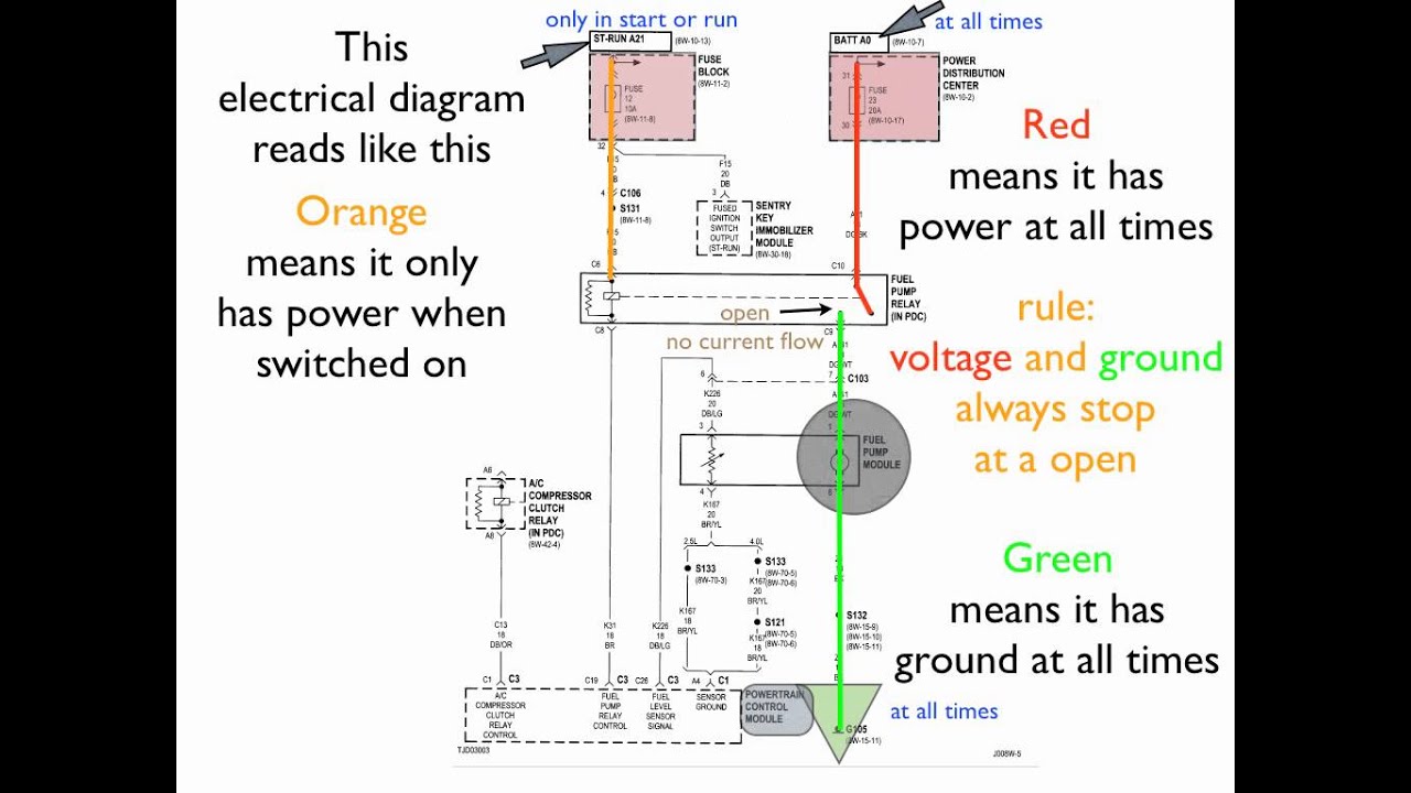
How To Read An Electrical Diagram Lesson 1 Youtube Electrical Diagram Electricity Diagram
Here are some of the standard and basic symbols for various components for electrical schematics.

. Remember that you are using a single line to represent multiple conductors. Diagrams start at the top of the page with the incoming source of a systems power. Circuit Diagram Connections.
Electrical Diagrams Electrical Layouts plans Electrical Schedules. In Figure 1 main low voltage distribution board consisted of five sections ie. Cubicles is shown in the form of single line diagram SLD.
Nowadays usually FUNCTION LOCATION -PRODUCT principle for creation of project tag for equipment is used according to IEC 81346. Example of single line diagram. Basics 8 AOV Elementary Block Diagram.
If they do connect they will cross and a dot will be seen at the point where the lines cross. The most common scale for commercial projects is V8 l-O 1100 metric. Diagrams show the electrical path device wiring and sequence of operation device relationship or connections and hookups of the electrical installation.
Electrical plans in commercial spaces are generally drawn at the same scale as the floor plans. If they do not connect one will be shown looping around the other in a semicircle. Scales accordingly of verify scales this sheet adjust if not one inch on bar is one inch on original drawing 0 1 miscellaneous electrical upgrades xxx abbreviations notes.
First you should know the common symbols used in an sld. Basics 10 480 V Pump Schematic. Basics 6 72 kV 3-Line Diagram.
Electric Motor Controls G. For this reason electrical power grids are most commonly represented in a single-line diagram format. 20 rows How to read one-line diagrams.
A node is simply a filled circle or dot. These include a one- line power distribution schematic a wiring diagram and electrical control drawings. Rockis 2001 Numerical Cross-Reference Systems Numerical cross-reference systems are required to trace the action of a circuit in complex line diagrams.
Wires may cross each other on an electrical drawing but that does not necessarily mean that they connect. All points along the wire are identical and connected. Dashed rectangles are most often designation for so called location.
A one-line diagram or single-line diagram is a simplified notation for representing an electrical system. The high-voltage winding is rated 69 line to- line kilovolts kV and The low-voltage winding is rated 138 line-to-line kilovolts. But you can also use the alternate rectangle symbol in the drawing.
The one-line diagram is similar to a block diagram except that electrical elements such as switches circuit breakers transformers and capacitors are shown by standardized schematic symbols. Electrical symbols are typically fed from the top. Each line in a line diagram should be numbered starting with the top line and reading down.
Basics 5 480 V MCC 1-Line. Circuit diagrams or schematic diagrams show electrical connections of wires or conductors by using a node as shown in the image below. However in complex installations the scale might be increased to V4 l-O 150 metric.
Details in blueprints either give a close up perspective a different perspective or a combination of the two. Basics 7 416 kV 3-Line Diagram. This means each transmission or distribution power line appears as a single.
Familiarize with Standardized Electrical Symbols. Starting at the top you will notice that a. How to read Single Line Diagram How to Follow an Electrical Panel Wiring Diagram Is video me electrical drawing paddna sikhenge Diagram ko kaise read kiya.
94 tripping or trip-free relay 93 field-changing contactor 92 voltage and power directional relay 91 voltage directional relay 90 regulating device 89. Basics 11 MOV Schematic with Block included Basics 12 12-208 VAC Panel Diagram. Basics 3 416 kV Bus 1-Line.
When analyzing power grids on the transmission or distribution scale however showing each and every conductor in electrical schematic form would make the system diagram needlessly complex. Resistors are the fundamental components of electrical schematics. When three or more lines touch each other or cross each other and a node is placed at the intersection this represents the lines or wires.
Electrical one line diagram design. Unless otherwise noted the impedance shown on a one-line diagram is based on the transformers OA rating. An electrical one-line diagram is a representation of a complicated electrical distribution system into a simplified description using a single line which represents the conductors to connect the components.
The note Z76 indicates that the impedance of the transformer is 76. Electrical drawings as per their purposes usually divide to main types as follows. Main components such as transformers switches and breakers are indicated by their standard graphic symbol.
In this Video we have demonstrated how to read and understand electrical Single Line Diagram also called as Power Flow DiagramWe hope this video is useful. Common rules help to quickly simplify the operation of complex circuits. They are usually represented by zig-zag lines with two terminals extending outward.
Basics 4 600 V 1-Line.

Electrical Symbols On Wiring And Schematic Diagrams Electrical Symbols Electrical Circuit Diagram Electrical Schematic Symbols

Learn To Read And Understand Single Line Diagrams And Wiring Diagrams Single Line Diagram Line Diagram Learn To Read

Wiring Diagram Everything You Need To Know About Wiring Diagram Electrical Wiring Diagram Electrical Symbols Electrical Circuit Diagram

Example One Line Or Single Line Diagram Line Diagram Single Line Diagram Diagram

Electrical Wiring Diagrams For Air Conditioning Systems Part One Electrical Knowhow Electrical Wiring Diagram Circuit Diagram Electrical Symbols

New Single Line Diagram Symbols Diagram Wiringdiagram Diagramming Diagramm Visuals Visualisation Graphical Check More At Https Thebrontes Co Eletricista

Electrical Wiring Diagrams For Air Conditioning Systems Part One Electrical Knowhow Electrical Wiring Diagram Electrical Diagram Diagram

The 16 Best Basic House Wiring Diagram References Https Bacamajalah Com The 16 Best Basic House Wi House Wiring Electrical Wiring Electrical Wiring Diagram

Schematic Symbols Electrical Circuit Symbols Electrical Wiring Diagram Electrical Diagram

Pin On Follow Me On Social

Single Phase Wiring Diagram For House Http Bookingritzcarlton Info Single Phase Wiring Diagram For House Single Line Diagram Line Diagram Residential Wiring

Single Line Diagram Of Indoor Substation Single Line Diagram Line Diagram Diagram

Electronic Components Single Line Diagram Line Diagram Electronic Labels

Reading Single Line Diagram Line Diagram Single Line Diagram Single Line

Pin On Energy And Power

Single Line Diagram Of Power Plant Line Diagram Single Line Diagram Single Line

Piping And Instrumentation Documents Instrumentation Tools Single Line Diagram Piping And Instrumentation Diagram Line Diagram

Electrical Single Line Diagram Line Diagram Single Line Diagram House Wiring
Our 4kw Grid Tied Solar Power System A Real Life Example Solar Power System Solar Panels Best Solar Panels